What Is Heavy Steel Fabrication and How Does It Work?
Heavy steel fabrication turns engineered designs into load-bearing structures, equipment, and industrial assemblies. It involves thick plates, large sections, precision cutting, forming, welding, inspection, coating, and controlled delivery. The work often begins with a digital model. It ends beside a crane, a transport trailer, or an operating plant.
The scale is substantial. World Steel Association’s World Steel in Figures 2024 reports approximately 1.892 billion tonnes of crude steel production worldwide in 2023. That volume supports construction, energy, transport, mining, and infrastructure projects. Yet production volume does not equal fabrication quality. A 25-millimeter plate still needs correct identification, storage, edge preparation, and weld control. AISC guidance, AWS D1.1, and ISO 3834 provide important benchmarks for design coordination, welding quality, and inspection. Non-destructive testing may reveal internal flaws invisible to the naked eye. Small errors can become expensive problems.
Charles J. Carter, former president of the American Institute of Steel Construction, has emphasized, “Steel is a material that can be reused and recycled.” That principle matters, but it is not the whole story. Fabricators must also manage heat distortion, tolerances, traceability, surface preparation, and transport limits. No workflow is flawless. Shop drawings can conflict with site conditions. Delivery assumptions can fail. This guide explains what heavy steel fabrication involves, how each stage works, and where practical judgment remains essential. The process is highly controlled, but never entirely mechanical.
Heavy Steel Fabrication: Scope, Materials, and ASTM A992’s 50 ksi Yield Strength
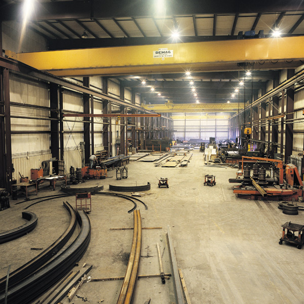
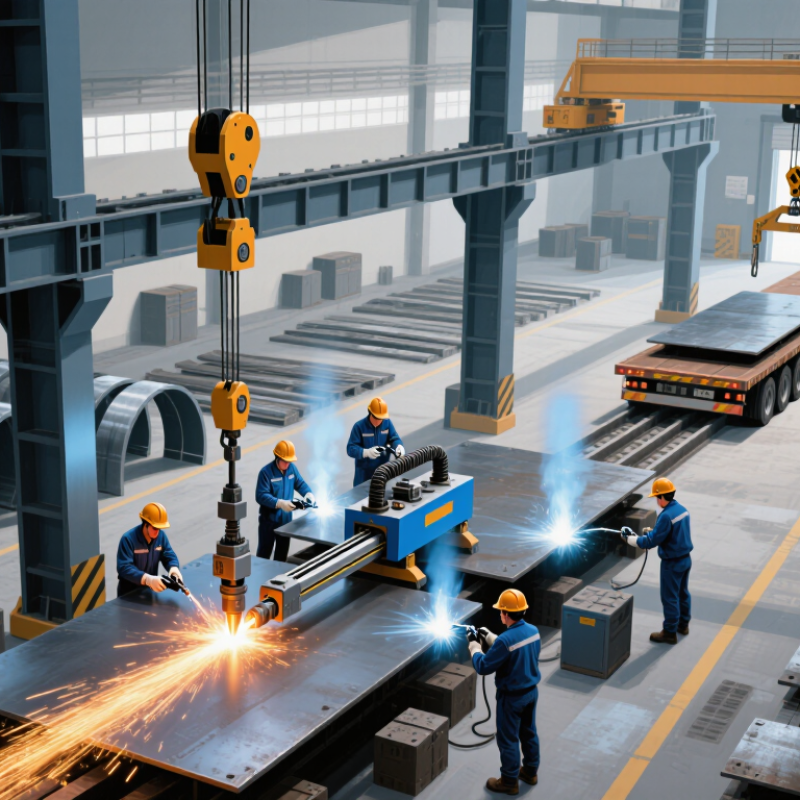
Heavy steel fabrication covers the cutting, forming, welding, and inspection of large structural members. These include columns, girders, trusses, bridge components, and industrial frames. The work often begins with digital drawings, material certificates, and a cutting plan. Operators then use saws, thermal cutters, press brakes, and submerged-arc welding equipment. Heat control matters. Excessive heat can distort long members and complicate final alignment.
ASTM A992/A992M is widely specified for structural steel shapes. It requires a minimum yield strength of 50 ksi, or 50,000 pounds per square inch. Its minimum tensile strength is 65 ksi. That difference gives engineers useful design capacity and deformation control. The material still needs traceability, dimensional checks, weld procedure qualification, and visual or ultrasonic inspection. The 2024 World Steel in Figures report recorded about 1.892 billion metric tonnes of crude steel production worldwide in 2023. This scale explains the industry’s pressure for efficient fabrication, but volume does not replace inspection. A heavy member may look straight while carrying hidden weld defects. That assumption is risky. In practice, fit-up tolerances, connection access, and lifting points deserve early review. Some projects still treat them as late details, which can create expensive rework. Workers also need practical clearance around weld zones, because laboratory strength values do not remove site-level handling risks.
Heavy Steel Fabrication: Materials and Yield Strength
This chart compares the minimum specified yield strength of widely used structural carbon and low-alloy steels. ASTM A992, commonly used for wide-flange structural shapes, has a minimum yield strength of 50 ksi.
Design Review and Detailing Under AISC 360 and AWS D1.1 Requirements
Heavy steel fabrication begins long before cutting, drilling, or welding. Design review must connect structural intent with practical shop conditions. Under AISC 360, engineers check strength, stability, serviceability, connection behavior, and required material specifications. They also verify load paths through columns, girders, bracing, and base plates.
AWS D1.1 requirements guide welded joint details, qualified procedures, welder qualifications, inspection, and acceptance criteria. A careful review examines weld access, joint preparation, backing, distortion control, and inspection locations. Detailing teams convert approved calculations into clear fabrication drawings. These drawings should show member marks, dimensions, bolt grades, hole types, weld symbols, and erection tolerances. A small missing dimension can delay an entire assembly. It happens more often than people admit. Field experience suggests reviewing connection geometry at full scale, especially around stiffeners, splice plates, and crowded beam ends. Analysis may be correct, yet the connection may remain impossible to assemble.
Tips:
Compare drawings against the latest design criteria before release. Confirm every weld symbol matches the intended joint and AWS D1.1 requirements. Keep revision clouds visible. Ask the fabricator whether tools can reach each weld. Record decisions, assumptions, and unresolved items in the review log. A second review is valuable, but it is not infallible. Details can still need adjustment after trial fit-up. Reliable work comes from documented checks, qualified personnel, and honest communication between engineering, detailing, fabrication, and inspection teams.
Cutting, Forming, and Fit-Up of Heavy Steel Components
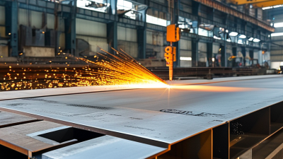
Heavy steel fabrication turns engineered drawings into load-bearing components through controlled cutting, forming, and fit-up. Large beams, plates, columns, and frames require accurate measurements before any torch or saw begins. Fabricators verify material grade, thickness, grain direction, and cutting allowances. Computer-guided cutting improves consistency, but skilled inspection remains essential. Heat can distort steel edges. Cutting too quickly may create rough surfaces or unwanted stress.
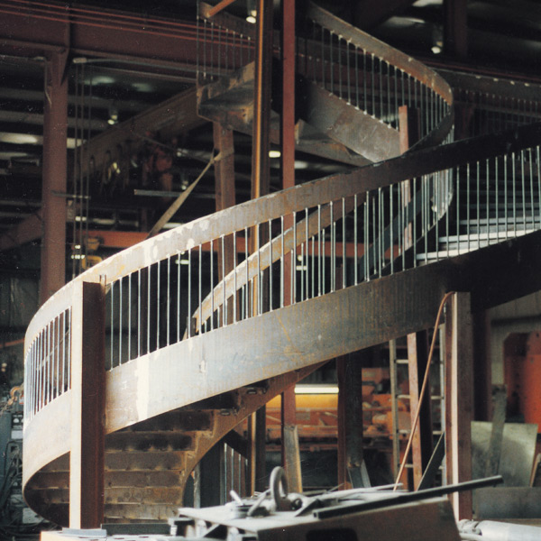
Forming changes flat steel into curved, angled, or rolled shapes. Press brakes, rollers, and controlled heating help achieve the required geometry. Operators monitor springback because steel may move slightly after pressure is released. Small deviations can affect later connections. Fit-up brings prepared parts together using clamps, temporary welds, and measured reference points. Workers check gaps, squareness, alignment, and bolt-hole positions before final welding. The structure must hold its intended shape during this stage. That is not always easy.
Tips:
Keep marked reference lines visible after cutting. Measure diagonals to confirm frame squareness. Use temporary supports when components shift under their own weight. Clean mill scale from critical weld areas. Never trust one measurement alone. A second check often catches an expensive mistake. Fabricators should record inspection results and review unclear drawing details before proceeding. No workflow is flawless. Even experienced teams can overlook a small offset, especially when several heavy components appear identical. Careful fit-up, patient communication, and realistic tolerances make the final assembly safer and more dependable.
Dimensional Inspection, Nondestructive Testing, and ISO 3834 Quality Systems
Heavy steel fabrication turns plate, sections, and forgings into structures that carry serious loads. The work may involve frames, pressure-bearing assemblies, bridges, or industrial platforms. Accuracy begins before welding starts. Engineers define tolerances, reference points, weld categories, and inspection stages from approved drawings. On the shop floor, inspectors check plate thickness, hole locations, squareness, and alignment. A laser tracker or calibrated measuring tool can reveal small deviations before they become expensive repairs.
Dimensional inspection is not merely a final measurement.
It follows the work as parts are cut, fitted, welded, and stress relieved. Inspectors record readings against controlled documents, not personal judgment. If a beam is four millimeters out of position, the team investigates its cause and decides whether correction is safe. That decision needs experience. Heat distortion can change geometry after welding, especially in long, restrained assemblies. Ignoring this risk is a common, costly mistake.
Nondestructive testing examines weld integrity without damaging the finished component. Ultrasonic testing can locate internal flaws, while magnetic particle or liquid penetrant testing can expose surface cracking. Radiographic testing may support critical weld evaluations when project requirements demand it. ISO 3834 strengthens this process through controlled welding procedures, qualified personnel, material traceability, equipment calibration, and documented records. A checklist alone is not competence. Some inspection plans look complete but miss access limits, temperature effects, or unclear acceptance criteria. Careful teams review those weaknesses before production, because quality systems must work in real workshops, not only in audit folders.